iMac G4 20" / Apple Cinema Display Parts List:
iMac G4 20" (Can be broken)
Apple cinema display 20" with PSU
5 wire resistive touchscreen
5 pin male to female touchscreen extension cable
Tools:
Rotary dremel with many cut off blades and sanders
Tin snips
Needle nose pliers
Mini screwdriver set
Allen wrench for cinema display stand
Full set torx screwdrivers or attachments
Soldering iron with solder
Wire cutter and stripper
Pliers
Duct tape
Gorilla glue
Cold weld
Multimeter with continuity check
Several sheets of grey styrene
I. Opening the Apple Cinema Display (This site is an Excellent Resource)
- remove stand by first unscrewing Allen bolt on each side then the 3 small torx-6 screws on underside of stand. Pull to remove
- insert a small flat screwdriver and pry off the white side panels on both sides
- disconnect the power/brightness panel
- unscrew all the mini screws
- use a mini screw driver to lift off side metal panels
- unscrew top large screw on both sides
- use flat mini screw driver to pull on sliding tabs on both sides at the bottom of the monitor. Pull tabs out - monitor should open
- disconnect 2 pin front led indicator
- slide monitor out feeding the cable through the hole in back until entire monitor is free.
 |
| Courtesy of The Ignition Project |
II. Disconnect the cable. The white cable splits off into several connectors that plug into the monitors boards.
- disconnect the black power connector by pressing down the latch
- disconnect the 5 pin cable from control board with needle nose pliers
- unplug the mini USB and FireWire cables that come from rear cable
- disconnect the 30 pin JAE connector that plugs into LCD by pressing in on clip on both sides simultaneously
- remove cable that attaches JAE connector and connects immediately to control board using needle nose pliers
III. Free the cable
- using wire clippers or scissors all outer shielding (tan plastic) must be removed from cable. remove all string.
- the big plastic block can be removed by slowly cutting with wire clippers or dremeling with cut off blade VERY carefully
- in the end you should wind up with 4 independent cables surrounded by silver mesh ending in 4 white plugs
a) The 30 pin JAE plug (with it's attachment) joins up with the 5pin connector to form 1 cable ending with DVI connector
b) The power cable (black latch at one end, other end plugs into PSU)
c) FireWire cable
d) USB cable

IV. Opening the iMac monitor
- unscrew 3 torx-6 screws at bottom of monitor housing (be careful not to strip the screws)
- slide out front which should contain the LCD itself
- disconnect the wires including front led (try not to damage for later use), microphone, inverter cable, and 30 pin JAE connector to LCD
- use torx screwdriver to remove four screws holding bezel onto neck
- remove wireguard
- slide wires through hole and place monitor housing to the side

V. Open base
- almost all torx except for bottom plate - phillips. will not get into, can remove everything (would leave drive tray)
- at top unscrew and free neck from base (save all screws)
VI. Wiring the neck
- There are two options here I detail the differences in this post. I'll discuss the one I went with the "hybrid method"
- Open the neck using taped together miniscrewdrivers
- Find the microphone/led cable. It is labelled. The lcd side breaks into two parts. One with 2 wires (LED), one with three(microphone)
- This wire is tapped to another inside of the neck. Gently cut the tape holding the wires together.
- Cut this wire in half inside the neck and remove the cut wire from both ends of the neck. (There is no use for these very small wires and this cable is the same size as the larger gauge power cable wires which will be taking its place).
- Cut the connector off the black power cable.
- Place the 3 wires (without the connector) into the neck start at the bottom hole and then through the top hole.
- Pull through so that there is at least 18" of wire on the lcd side of the neck.
Close and seal the neck in the same fashion it was opened
- Remove the native iMac's 30 pin JAE connector by cutting the wires. (The pins in the connector are too fragile and not worth saving).
- Remove the pins gently from the iMac's inverter connector.
- It should now look like:
 - Take the USB, DVI, and 5pin connector cable fome the apple cinema diaplay and cut off at least 12" from the LCD side.
- You will now need to solder the power connector back on from where it was cut.
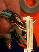
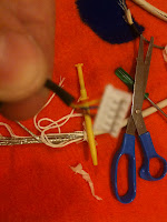
- Solder the iMac G4's black wire (the one that has 3 wires that split into green, red, and shield) onto the ends of the Apple Cinema Displays JAE connector wires. Use the soldering iron itself to melt the plastic covering as these wires are otherwise impossible to strip.
 - Solder 5 wires from the iMac G4's Gray cable onto the ends of the Apple Cinema Display's 5 pin connector.
[Although it probably doesn't matter which color wire you choose as long of you solder the bottom end onto the same wire, I used the wires that served the same function in the native iMac.]
- Solder the USB onto 4 remaining wires from the gray cable
- Solder 5 wires from the inverter cable to the male end of the 5 wire touch screen extension cable.
- Repeat this process for the bottom half. Making sure to solder the same wire to the bottom half that you chose for the top. REMEMBER TO PUT THE DVI CABLE THROUGH THE HOLE IN THE BASE BEFORE YOU SOLDER.
- Wiring the neck is detailed in greater depth in this post
VII. Making the Monitor casing
- Unscrew the metal bracket that pokes out of the back of the Apple Cinema Display's Case
- Using a flat screw driver pry up the metal plate that is glued down to the back of the Apple Cinema Display's housing.
- Remove the inverter from the iMac G4's monitor housing
- The inverter is held on by several screws
- Using needle nose pliers pull out the 4 bolts in the iMacs back case that the inverter screw into
- Place the Apple Cinema Display inside of the iMac G4's housing. With the bol's removed it should fit flush and snug
- Turn it over - The back of the apple cinema display should be visible in the iMac G4s hole where the neck used to be
- Using a pencil trace that hole.
- Using a flat head screwdriver you will need to separate the iMac G4's metal housing from the white plastic it is glued to. (To do this you will likely snap the white plastic several times).
- Using tinsnips and a rotary or multimax dremel cut out a bracket from the center of the metal casing that includes the circular neck attachment. Be patient, this is difficult to cut and will take some time.
 |
| Comparison of original and new bracket |
 |
| Further Cut-down bracket |
- Using tinsnips cut out the hole that was traced on the back of the apple cinema display
- Place the neck through the hole to ensure that it will fit
- If small modification is needed use the dremel with either a cutting or sanding part.
 |
| With hole cut |
- Position the bracket inside the apple cinema display and use the screws to secure the new monitor housing in place.
- Make sure that the monitor is not rotated.
- Trace around the bracket to record the proper position
- Remove the monitor and bracket from the neck
- Using grey styrene cut out small fill-ins for the two lines that come off the new hole as well of a circular fill in to the Apple cinema display's original hole
- Glue these in place
- Now position the bracket in place and Cold Weld vs Gorilla Glue the new bracket firmly down to the inside back of the apple cinema display's housing
VIII. Further Modification for use with touchscreen (This is only for people who wish to add the same touchscreen I did).
- Cut further weight from the bracket as documented above
- Trace the touchscreen dimensions on the front of the Apple Cinema Display's Bezel
- Dremel out the inner portion of the front bezel
- Fuse the LED cables from the two different monitors
- This step is documented in great detail in this post.
VIII. Putting in the LCD
- Place the cables through the bottom opening of the Apple Cinema Display
- Reconnect to the LCD
- Lift the LCD screen into the bezel. As you do this try to keep the wires from stacking on top of each other (This can be a pain) otherwise it will not close easily. (If you are using the touchscreen, try to leave that connector/cable accessible towards the bottom of the screen)
- If you are using the touchscreen - place it in the modified front bezel and wrap the ribbon cable inside the bezel around the LCD and connect it to the 5 pin connector.
- Leave the on/off brightness cable sticking out the side
- Connect the LED cable (if you are using the modified original iMacs, wrap the ribbon cable around the bottom of the LCD.
- Push in the pins at the bottom to close the display. You should not have to use any force. If you do readjust the wires behind the LCD.


